Want to check out our tractor maintenance videos? Click here to see what we've got!
Your link arms will not lower. It’s a frustrating problem.
We commonly associate hydraulic problems with poor pump performance and reduced or slow lift capacity. However, we get quite a number of people reporting that their link arms won’t lower.
We’ve had an email from the owner of a Massey Ferguson 35 who has this problem, so we’re going to take a look at what could be the problem and what needs to be done to get the system working again.
Lift Arm Shaft
The rate of drop of the arms should be set so that the lower links will just fall under their own weight when lifted by hand. This is altered by adjusting the cap screws in the ends of the lift arms shaft.
If the screws are tightened too much, not only will it prevent the arms from lowering but it can also cause erratic action of the hydraulic system.
However, if a heavy implement is attached to the linkage and the arms will still not drop then it is likely to be related to the pump control valve. We first need to uderstand how the position of the control valve raises and lowers the arms.
The Pump And Control Valve
The lower part of the pump is immersed in hydraulic fluid. When the control valve is open it allows fluid to be sucked up into the pump and then on into the discharge passage (to pressurise the lift cylinder and lift the linkage arms).
The contol valve slides to regulate the supply of fluid to and from the lift cylinder, the degree of which depends upon the relative settings of the manual control levers (and also by any control exerted automatically by the hydrauilc control mechanism).
The sliding control valve is essentially seperated into two compartments, one facilitating fluid inlet to the pump and the other compartment allowing an outlet from the high pressure chamber.
NOTE, the control valve is always held towards the drop position by a compression spring.
- When the valve slides forward, its inlet slot passes within the suction chamber, hence the pump can draw fluid and pressurise the fluid into the lift cylinder.
- When the valve is positioned centrally, both the inlet and outlet slots are positioned outisde of their chambers and hence the oil is locked in the system and the linkage arms remain stationary.
- When the valve slides rearwards (by the force of the compression spring) the outlet slots are brought within the discharge chamber, thereby permitting oil to drain from the system (lift cylinder) back into the sump.
The rate at which oil drains from the system depends on how much of the outlet slot is moved into the discharge chamber. In fact there are two pairs of slots in the discharge end of the control valve. The second pair of slots are positioned further along the control valve, so if the control valve is moved further rearwards then all four slots discharge oil and thus the rate of drop of the lift arms increases. The second pair of slots are also larger.
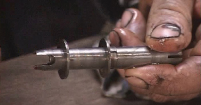
Inlet slots at the rear end of the vavle (LHS of photo), small outlet slots at front end of the valve (RHS of photo).
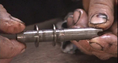
Control valve rotated 90 degrees to previous photo. Now we can see the second pair of larger outlet slots (RHS of photo).
What Can Go Wrong?
General Information
The control valve needs to be oil-tight to the bore of its sealing washers (the washers seperate the suction and discharge chambers). The fit between the washers and the control valve is therefore extremely precision as it must seal under pressure but also facilitate the control valve to move.
To prevent the control valve from sticking there is an oscillating mechanism. The oscillator is driven from one of the pump eccentrics as the drive shaft rotates. It is not uncommon for the square end of the oscillator push rod to be rounded off. This would cause the oscillator to be inoperative and so the rod would need to be replaced.
The exteme accuracy of fit between the control valve and its sealing washers means that any small particle of dirt could cause the valve to jam. Extreme care should therefore be taken with cleanliness of the system.
- Cleanliness of the fittings should be considered when connecting to the hydraulic ports (eg. connecting a tipping trailer or front loader).
- Change transmission fluid every 750 hours (or annually). Clean the pump filter (if fitted) and remove any deposits on the magnetic transmission casing drain plug.
Compression Spring And Control Linkage
Failure of the compression spring would mean that the control valve will not be pushed rearwards into the ‘drop’ position. Failure of the compression spring is quite common.
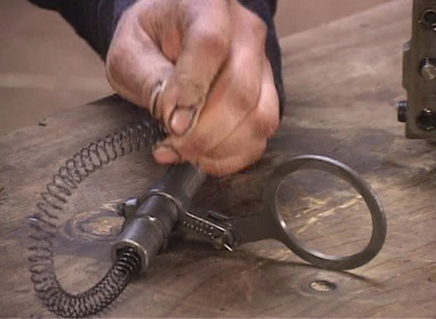
The oscillator spring, although not a very strong spring, is quite long. It is possible to hold the spring pressure by hand whilst removing the retaining circlip.
Also, it is possible that a failure/problem/jamming of the internal control linkages would prevent the control valve to move rearwords into the ‘drop’ position.
Water Or Condesation In System
We’ve had a few people contact us to say that they have had probelms with milky oil (condensation built up over time and mixed with the water) and this, they suspect, has been the cause of their lift arms sticking up. One owner reported the arms sticking whilst the temperature was below freezing. Another owner reported the lift cylinder and its piston rusted together after just 4 months of not using the tractor – this owner had the milky oil and had to remove the top cover to free the piston.
Isolating The Problem
It is possible to drain some of the hydraulic fluid and remove the right hand transmission casing inspection cover to take a look inside the tractor. Do not put your hands through the inspection hole if the engine is running. It should be possible to see if the levers are moving the control valve and to see if the spring is returning the control valve to the rearwards (drop) position.
Removing the stand pipe would also isolate the pump, control valve and control linkage mechanism as the problem. i.e. if the stand pipe is removed then the problem is either associated with the lift cylinder itself or the lift arms binding. Beware, even with the engine stopped, the hydraulic fluid in the stand pipe could be pressurised.
It is possible that the lift cylinder seizes in the ‘up’ position if the tractor has not been run for some time, rusting in place due to excess moisture in the oil and the transmission casing. An example of this occuring is given in the comments section of this page.
Making The Repair
Obviously the necessary repair depends on what you suspect the problem to be.
Earlier in the article we looked at what to do to set the lift arms to prevent them from binding.
Repair of the control valve and its oscillating mechanism will require removal of the hydraulic top cover to access and strip the pump components. This is an involved process and you may find the MF35 Hydraulics Troubleshooting And Repair DVD helpful to guide you through this process.
This article was based around the Massey Ferguson 35 tractor. The information will also be useful for many other models that have a similar control valve and hydraulic system.

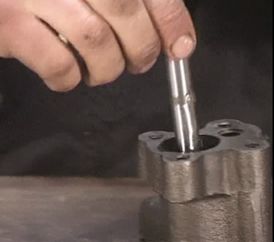


Greetings from Ontario, Canada.
I had the same problem on my MF35 FE. In my case, the problem was the hydraulic cylinder that lifts the arms up. At the time the tractor had not been used for about 4 months, and due to moisture in the hydraulic fluid, the cylinder ‘froze’ (rusted) in the ‘up’ position.
I solved the problem by removing the heavy cover under the seat, removing the cylinder, and with convincing persuasion (wood blocks, banging, and penetrating oil) was able to free the cylinder. Regular maintenance has since prevented a re-occurrence.