Want to check out our tractor maintenance videos? Click here to see what we've got!
Many Standard 23C diesel engines have the ‘Thermostart’ heating and vaporising coil fitted in the inlet manifold. Effective as this is, FE-35 tractors sold for use in areas of the world where extreme cold temperatures are expected were often fitted with ‘cold climate heads’ that have individual heater plugs for each pre-combustion chamber. Tractors equiped with this system do not have the thermostart system fitted.
It is still possible to get the glow plugs (or alternatives) from some suppliers, but they are becoming more difficult to source in some contries. We are going to take a look at the system, the components, the wiring diagrams and an alternative system built from more easily obtainable components that offers some advantages to the original system.
We’ve got some really helpful photos and diagrams to show you exactly what to do if you need to work on the heater system.
——————————————————————————————————
Per owns a cold climate FE-35 over in Canada, and he’s written a comprehensive article about the system on his tractor and how he has converted it. The following information summarises Per’s article, but to read the full article then we would recommend taking a look at Per’s page on the subject (and there’s lots more great stuff on his website too!).
If you are able to source the original type of glow plug and ballast resistor (or manufacture one) then you would have no need to change, but this information may be useful for those of you who cannot source the original equipment.
The Glow Plugs
The heater plugs as specified in the MF manual are…
KLG. Z 161/3 (1.7V. 38 amps)
superseded by…
Lodge D.T. 14 L-1.7V (1.7V. 38 amps)
KLG. GF. 205.T (1.7V. 38 amps)
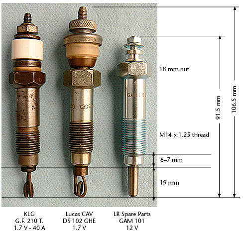
The two plugs on the left and centre of the picture below are what was removed from Per’s tractor. The plug in the right of the picture is the new replacement plug that also fits these engines (and comes from a Land Rover engine). However, the new plugs are 12V, so it would be necessary to convert to a parallel wiring system if you use to this type of plug.
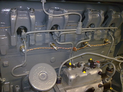
The old plugs are easily identifiable by the insulating washer (even when fitted to the engine).
The Originals, And Replacement Plug
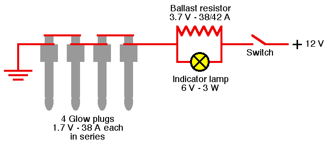
Original Wiring Diagram
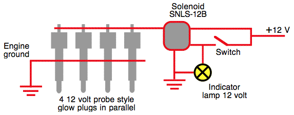
New Wiring Diagram
Wiring the new glow plugs in parallel also gives us an advantage. Using the old series wiring system means that if one plug fails, then none of the others would work either. Parallel wiring means that if one plug were to fail then the other three would still be receiving current and hence working.
The other train of thought on this is that if a plug blows when in series you will know something has gone wrong and you will replace the faulty plug (there is a warning lamp on the original system to indicate this – if it doesn’t light). The potential disadvantage of parallel wiring is that you don’t realise when one plug blows, then some time later the next plug may blow. The operator may then think that starting performance is slowly deteriorating and may not realise it is the plugs.
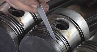
It is also possible when the corkscrew / coil type of glow plugs burn out, that the element can drop into the pre combustion chamber and get into the cylinder itself. The probe type of plugs are much less likely to suffer from bits falling off.
The Ballast Resistor
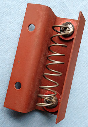
The ballast resistor was originally fitted to prevent over-loading during the initial heating period.
The ballast resistor is not necessary with the new plugs wired in parallel, as each plug is 12 volts.
The ballast resistor in the photograph above was manufactured for Per by one of his friends. His friend used 14 gauge Nichrome wire and made four new fibre washer insulators.
We’ve also found that Land Rover parts suppliers stock balast resistors (link to balast resistor part). We haven’t checked to see if this component is the exact same physical size, so you would need to do your homework on this one.




Hi guys could someone give tell me what I need. I have a 203x industrial and it’s getting near impossible to start. So I’m thinking of replacing injectors and glow plugs but I’m unsure of part numbers. Any help is greatly appreciated.
Hi. I have a massey ferguson 35x perkins 3 pistons starting hard to live in the mountain area, could you tell me for a perkins engine 3 pistons how could i mount the glow plug
Dave , do you still have the engine ?
Hi John,
I would think you would need some big solar system and a very expensive batter to keep up with the electrical demand of a block heater.
Could you use another heat source for the job? I guess you would need to duct warm air to the tractor and enclose the engine in some sort of jacket, so not easy to do.
I have a 120 volt engine block heater, but no way to get power out to my fields where the tractor is stored. Is there any solar device that can be used to heat the block?
Thanks so much for the glow plug info on the 23 c engine , installed yesterday and it worked like a charm.
I have 7 good old style 6 v if anyone is interested . I have a complete spare engine as well less the injector pump.
Wow exciting information but in cases of blown plug with bit falling into the linning it cause serious damage to the sleeve and piston in the parallel system.can’t it be avoided? .great piece of information thanks Ferguson
I have a standard Dexta can I do anything to make it easer to start
Hello,
Groung polarity has no effect on the circuit as the glow plug are resistive components – no electronics.
Great piece of information lets hope a adaption can be done with out great problems.
Good day: The heater plug wiring diagram is interesting, but I have a positive ground electrical system. How would I wire the replacement heater plugs?