Want to check out our tractor maintenance videos? Click here to see what we've got!
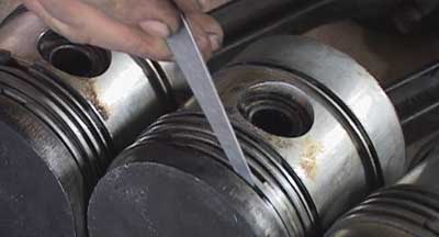
Checking and setting the valve clearances is a job which often gets overlooked. Over time, and with wear in the valve seats, the valve tip clearance becomes reduced. For this reason, it is important to check the valve clearances.
For a full explanation of these procedures, you may find our Perkins A3.152 Engine Rebuild DVD useful.
The Question…
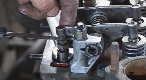
I am setting the valve clearances for the first time ever on my MF135. Can I just check the process – I presume you use a spanner to secure the tappet rod at the bottom, then loosing the lock nut above that and then adjust the clearance by turning the bolt at the top? Am I correct in thinking that this whole assembly is free to rotate, presumably to even out wear on the head?
The cold clearance should be 0.30mm for both inlet and exhaust – the book says to get the TDC line in centre of flywheel inspection hole and check numbers 1,2,3 & 5 – then rotate the flywheel 360 degrees and check numbers 4 & 6 (I presume all numbering is from front of engine back?). I have been surprised to find on my initial check that No.1 valve was close to 0.30mm but every other valve was more or less completely “tight”. Is that unusual or am I doing something wrong?
The Answer From VTE…
Firstly, yes all numbering is from the front of the engine back.
As for the “tight” valve clearances, this is not unusual to occur as the engine valves wear against their seats. Everytime the valve clatters against its seat it slowly wears until eventually the vavle starts to receed further into the head which is what narrows the vavle tip clearance. This is commonly known as “valve seat regression”.
This is why the valve clearances should be checked and adjusted at the appropriate service interval. The recommended vavle tip clearance is 0.012 inches (or 0.3048 mm).
You are correct that the cam followers do rotate during operation, this is indeed to prevent them from wearing unevenly.
Another thing to check before you tighten down the rocker shaft is the oil flow setting to the bearings. This will have been calibrated and the punch mark scribed in the factory. The groove in the shaft needs to be lined up with the punch mark. If you look carefully at the photo at the top of the page, you can just see the punch mark that the groove has been lined up with.

I believe that it could not be a better explanation of what the author does. It was very helpful even to technicians of long experience.The only think I can say at the moment is to thank you very much for your assistance and I promise to share my experiences with you soon.
One of these is to find the point of TDC with No.1 cylinder on compression by the use of capillary glass tube with some quantity of coloured liquid connected with No.1 injector hole and move the c/s in both directions (slighlty) until the liquid is at the max. height in the capillary tube.