Want to check out our tractor maintenance videos? Click here to see what we've got!
Here are the data, specifications, dimensions, tolerances and the main tightening torque settings for the 3 cylinder Perkins A3.152 engine as fitted to the Massey Ferguson 35 tractor.
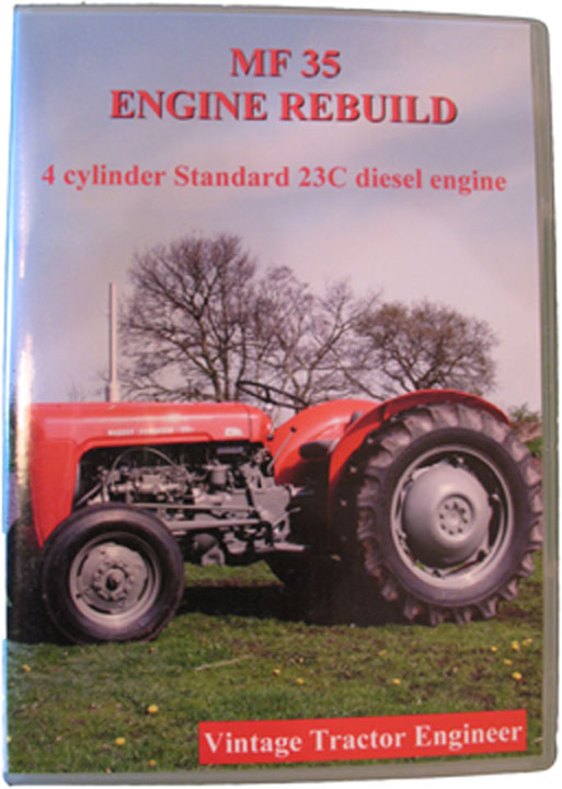
These specifications accompany our MF35 (3 cylinder Perkins) Engine Rebuild DVD, which you may find useful if you’re working on one of these engines.
Data Specifications
Cylinders 3
Bore 3.6” (91.44mm)
Stroke 5”
Displacement 152.7 cu ins.
Compression Ratio 17.4:1
Firing Order 1,2,3
Power 37 bhp
Location of No. 1 Cylinder, Front of engine
Cylinder Liners, Chrome plated
Fuel Pump Static Timing, 18 degrees B.T.D.C.
Letter On Fuel Pump Rotor, E
Letter on Hydraulic Head No. 1 Delivery Port, W.
Inlet Valve Opens, 13 degrees B.T.D.C.
Exhaust Valve Closes, 10 degrees A.T.D.C.
Valve Overlap, 23 degrees
Valve Lift, 0.36″
Tappet Setting (Hot), 0.010″
Tappet Setting (Cold), 0.012″
Tightening Torques lbs./ft
Cylinder Head Nuts, 55-60
Con. Rod Nuts, 70-80
Main Bearing Setscrews, 110-120
Flywheel Setscrews, 75
Balance Weight Setscrews, 50-55
Pressure Setting (injector bleeding pressure), 120 Atmospheres
Operating Oil Pressure, 25-30 p.s.i. or more at normal speed
Relief Valve Setting, 50-65 p.s.i.
Assembling Cylinder Head
When replacing the rocker assembly ensure the slot at rear end of rocker shaft is in line with the punch mark on the rear pedestal bracket. The relationship of this slot to the punch mark determines the quantity of oil delivered to the rockers and bearings.
Adjust inlet and exhaust clearances to 0.012″.
Adjusting Valve Clearances
Remove the rubber plug in the inspection hole in the left front side of the transmission housing adapter plate.
Rotate crankshaft until the T.D.C. line on the flywheel is in the centre of the inspection hole and No. 1 piston is on the compression stroke (both vavles fully closed).
Check and adjust clearances on Nos. 1,2, 3 and 5 vavles.
Turn crankshaft one revolution and repeat for Nos. 4 and 6 vavles
(T.D.C. mark visible through inspection hole).
Replace rubber plug in adapter plate.
Vavle clearances for both inlet and exhaust should be set to 0.010″ hot, and 0.012″ cold.
Oil Pump
Check clearance using a feeler gauge between maximum diamater of inner rotor and minimum diameter of outer rotor, clearance should not exceed 0.006″ (or replace/refurbish pump).
Clearance between driven rotor and pump body not to exceed 0.010″.
Placing a straight edge over top of rotor faces, measure clearance between top of rotors and surface of pump body – not to exceed 0.003″.
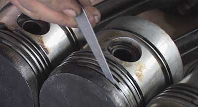
Piston Rings
Compression and oil control ring gaps should be within 0.009″ – 0.013″ (measured in a ring gauge of 3.6″).
Cylinder Liners
When the liners are fully in position, the top face of the liner flange shoule be 0.001″ – 0.009″ below the top face of the block.
Tolerances
Standard Crankshaft Main Journal Diameter, 2.7485″-2.7490″.
Big End Crankpin Diameter, 2.2485″-2.2490″
Small End Bush (internal diameter), 1.2505″-1.2515″
These figures are taken from the Massey Ferguson 35 Service Manual. Whilst every effort has been taken to reproduce these figures accurately, no responsibility can be taken for errors.


Hello:
I have recently acquired a MF 35 and would like to ascertain the tractor’s build date and serial number (plate is missing!).
The engine block casting number is 37111280 and the stamped engine serial number is 1958258. Assuming the engine is the original A3.152 Perkins, can someone tell me the other info?
Thanks,
PeterD
Hi Hal,
If you go over to this page…
http://vintagetractorengineer.com/2010/05/massey-ferguson-35/
…it gives examples of date based castings codes, so if you find a casting code on your tractor then you can use the information on that page to date the castings.
Steve
Fellas…Like the guys above i have a question.. I have two numbers 189 459 M1
& ckn1523M
But looking at the timeline of ananswered questions here i personally think the question is a waste of time…but i’ll ask anyway anyone know year based on those numbers…Hal/Spud island.
i removed the crank shaft ballance weights from a Perkins A3.152 and did not mark them, can anyone tell me which one goes in the front and back PLEASE.
Hey my original post was wrong, The sn# is c37111280 sorry, still need to know about what year and rebuild kit number if possible. The tractor is a 1960, and I think the engine is not original. thanks again Buddy
Hello, I have a MF35 3cy diesel. Serial #on block C57111280. Its smokeing and need to rebuild it. Can anyone tell me the year. I think my tractor is a 1960. Thanks Buddy
Hi all, I have a Perkins A3-152 in my MF 35 tractor. It has s/n 37111280J and wonder if anyone out there is kind enough to advise if this has cast or chrome liners? It needs an overhaul and wanted to order the spares before it gets stripped down, Thx in advance, Neil
I have what I believe to be a massey furguson 35 diesel delux with a perkins A3.152 engine only numbers I can find on left hand side are top of block by head CL185148 C below that the word MON O CYL below that A 19 1 about middle of block the number C 37111280 and on the bottom GKN1523 what is the year and rebuild kits that would work any info would be helpful