Want to check out our tractor maintenance videos? Click here to see what we've got!
The hydraulic top cover on the Massey Ferguson 35 (FE35 and TO35) is a heavy and difficult piece of metal to handle. It takes 2 people to remove the top cover and then it needs turning upside-down to work on it.
This bracket, in conjunction with a handle, makes removal of the hydraulic cover a one-man operation. Not only can the cover be both removed and replaced in a controlled manner, but it also provides a method of turning the cover upside-down in order to work on it.
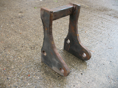
We cut the sides from 12mm steel plate, but a slightly thinner plate should be strong enough. A length of 25mm X 115mm box is used to fasten the plates together.
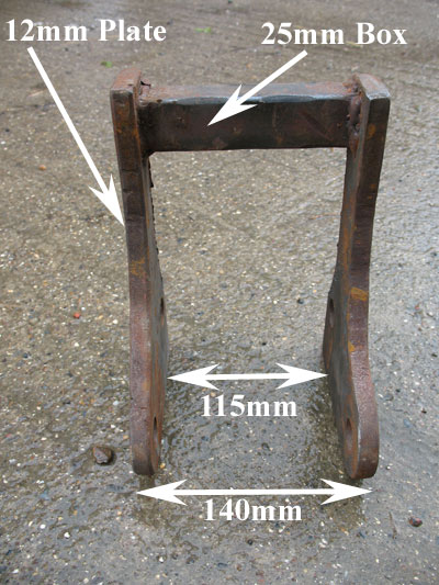
You don’t need to be too precise with the 115mm or 140mm dimensions, as there is plenty of margin for error.
Click on this link ” bracket001 ” to open a plan drawing of the side plates of the bracket. This is drawn to scale so you should be able to copy the shape straight onto your steel plate. We drilled both holes 3/4?, but it would give more flexibility if the hole marked on the diagram is drilled to 1? (or even slightly larger). A scale is indicated on the drawing so you can make sure your printer has printed it off to the correct size.
The Handle
The handle wants to be just a bit longer than the distance from the pivot point of the bracket (the point that the top cover hinges from the bracket). The handle doesn’t want to be any less than this, otherwise it will pivot back on itself and get difficult to hold.
It wouldn’t be a bad idea to get a second person to help you with the last bit of travel when flipping the top cover over. It is a heavy component, and as it comes over the vertical/blance point it will become progressively ‘heavier’ as it inverts and turns around the pivot point of the bracket.
CAD Drawing
Brian has sent us in a CAD drawing of the bracket which has some more accurate dimensions. Click this link to get the CAD drawing – Bracket for Hydraulic Top Cover Removal – Massey Ferguson 35.
Once the bracket is attached by the 2 pins and the handle is fixed to the top cover (on the seat fastening bolts) then you can flip over the top cover as shown in the video.
Many of you have made a bracket – Alan from Ontario has made a bracket and sent in some photos.
Dave’s Improved Design
Dave from New South Wales, Australia has also been busy designing and building his own bracket. This is an improved and more phosisticated diesign which gives more control of the initial lift of the top cover off the transmission housing.


We had this question come in from Gordon:-
What is the length and size of the square tubing for the top cover removal? I don’t see it on your “bracket” making page. From the video that I ordered, it looks to be about 3 1/2 feet long?
Is it on the video somewhere or on the bracket page and I missed it?
Vintage Tractor Engineer replies:-
I don’t think we published it on this “bracket page” for some reason.
Bascially if you just measure from the ground to the pivot point of the bracket (that is going to be used to flip the top cover over), then add on another 6 inches or so, that should be about right. The handle doesn’t want to be any less than this length, otherwise it will start to pivot back on itself and be difficult to hold.
The hydraulic top cover is quite a heavy component, so when you are flipping it over it wouldn’t be a bad idea to have another person there just to help steady it down the last little bit. When the top cover is in the vertical position exactly above the pivot point it is obviously easy to hold, and then becomes progressively more difficult to hold as it pivots further over.
Hi Bob, The same principal applies, but you will need to slightly alter the bracket to fit the 135. Also the plate which you make to attach to the top cover will need to have a hole cut into it so that it fits around/over the protrusion (of the draft spring/top link casting).
Steve.
I have a 1970 MF 135 3cyl perkins, will this bracket work on my top cover and also do you have any dvds to work on this tractor
Hi Mike,
We don’t make and/or sell them. In your case it may be easier to lift the cover with some gear from above. It is then just a case of turning the cover over without damaging anything.
Steve.
Hi,
I live in the sticks and am having problems getting the bracket made which help remove the hydraulic cover. Is there any chance that you may make ans sell these?
Mike
hi just wondering could you help me, i have a te 20, hydraulics are working up and down but no draft,if i put put a bar on the top link bracket where the spring is and move it it effects the arms from raising and lowering,confused???
Thanks
John
Ireland
[…] Hi Thomas, the scale drawings of the bracket for the hydraulic top cover removal are available here. […]
Hi Dean,
We charge the same shiping cost to the U.S., so the postage is covered thanks.
After removing the cap (right hand front corner of hydraulic top cover) and then pulling out the stand pipe, it is just a case of fastening the bracket to the tractor with some pins and then another pin through to connect to the end of the draft control spring, then fasten a long handle to the studs that hold the seat in position and then the top cover can be flipped over. The advantage of this is the one man operation and also the handle doubles up as a stand so the top cover is just flipped over backwards and sits there nicely inverted to work on.
Hope that made sense?
Other people sometimes just use a chain pulley supported from a suitably robust rafter or an engine crane to help lift off the top cover, but then the cover is to turn upside down in order to work on it.
Hope that made sense.
Steve Ridsdale (Vintage Tractor Engineer)
Hey. I ordered one of your DVD’s. My address is in the U.S., are we square on the shipping costs? If you got a moment, can you go ahead and tell me what the trick to flipping the top cover off is? I just unbolted the cover and set it aside, but that was about as heavy as I care to pick up.
Thanks,
Dean
The first thing that springs to mind is, have you positioned the position and draft levers to the correct side of the roller on the control vavle actuating lever?
If you remove the inspection plate on the RHside of the transmission casing you can see the control valve actuating lever and the roller. If you then have the engine running it is possible to move this lever (using a metal bar) and actuate the pump. DO NOT PUT YOUR HANDS INSIDE WHILST THE ENGINE IS RUNNING, BE VERY, VERY CAREFUL. If this raises the lift arms then you have done something wrong with the linkage system.
Steve.
Sir,I have a TO 35 with the hydraulics suddenly not working. I removed the top cover to change the gear oil that got contaminated with water – at this time the hydraulics still worked great. I had the top cover off prior to this event,& replaced it with no ill effect.
While lubricating the works in the top cover with WD-40, I noticed a round cam follower was pushed off the flat steel in which the round follower followed a curve. I gently pushed the round follower back so the described steel curve would be over the round follower. Working the controls I saw very little movement of the two flat steel fingers that operate the pump. After the top cover was reinstalled – in the same fashion as during it’s previous re-installation, the hydraulics did not work at all – not even the slightest of pressure on the piece the big piston in the top cover is attached to.
I had carefully removed silicon used to form a gasket for the top cover and wonder if a small piece of that may have clogged the pump, or, did I foul something up in the control linkage causing such little movement of the two fingers and that causing the pump not to actuate to move fluid? Any idea what I mucked up? Thanks for the reply – I need to get this working before the snow flies in Southern Illinois, US.
Hi
Can anybody tell me how to remove a TE20 hydraulic topcover ( all retaining bolts have been removed )it will lift a little way and then stop.
James